International Journal of Theoretical and Applied Nanotechnology (IJTAN)
ISSN: 1929-1248

Volume 2, Year 2014 - Pages 18-23
DOI: 10.11159/ijtan.2014.003
Alignment of Needle TiO2 Nanoparticles in Water
Atsushi Hasegawa1, Masamitsu Yoshiki1, Tsuguhito Nakano2, Kohji Abe2, Susumu Sato3, Tetsu Yonezawa4
1Joetsu University of Education, 1 Yamayashiki, Joetsu, Niigata, 943-8512, Japan
ahase@juen.ac.jp, masamitsu.6.23@gmail.com
2Department of Engineering Science, University of Electro-Communications, 1-5-1 Chofugaoka, Chofu-shi, Tokyo, 182-8585, Japan
tnakano@pc.uec.ac.jp, abe@pc.uec.ac.jp
3ARIOS Inc., 3-2-20 Musashino, Akishima, Tokyo, 196-0021, Japan
ssato@arios.co.jp
4Division of Materials Science and Engineering, Faculty of Engineering, Hokkaido University, Kita 13, Nishi 8, Kita-ku, Sapporo, Hokkaido, 060-8628, Japan
tetsu@eng.hokudai.ac.jp
Abstract - Alignment of needle-like nanoparticles in solution because of migration due to an electric field is observed using Rayleigh-Mie scattering. This is confirmed by the change in the signal form as a function of the scattering angle. It is clearly observed that the signal profiles between the aligned and non-aligned situations are different. The theoretical calculation of Rayleigh-Mie scattering based on a single spherical particle is used for analyzing the experimental data. The theoretical analysis is in good agreement with the result of experiment.
Keywords: Alignment, Rayleigh-Mie scattering, migration, alignment ratio.
© Copyright 2014 Authors - This is an Open Access article published under the Creative Commons Attribution License terms. Unrestricted use, distribution, and reproduction in any medium are permitted, provided the original work is properly cited.
Date Received: 2013-09-24
Date Accepted: 2014-02-24
Date Published: 2014-03-31
1. Introduction
The size and shape of nanoparticles are important parameters for technical applications. Hence, the size and shape are carefully controlled in the preparation of nanoparticles. The Transmission Electron Microscope (TEM) or the Scanning Electron Microscope (SEM) is used for evaluating the size and shape of nanoparticles. In the process of preparing these nanoparticles, we have a strong demand for the information of the size and shape of the particles at the same time. TEM and SEM are powerful tools, but preparing a sample takes time.
Conversely, optical scattering methods such as Rayleigh-Mie scattering are useful methods for measuring the size of nanoparticle. In general, if the diameter of scattering particle d is much smaller than the wavelength of incident light l and if d is larger than l, the former is Rayleigh and the latter is Mie scattering, respectively. Since there is no noticeable boundary, in this paper we use the word Rayleigh-Mie scattering. In Rayleigh-Mie scattering, the scattered signal intensity strongly depends on the particle size as a function of the scattering angle [1]. The size of the particle can be estimated from the analysis of the angular dependent signal. Theoretical analysis of the light scattering from spherical and the non-spherical nanoparticle has been performed for a long time. Several experiments relating for spherical particles have also been performed. But when non-spherical particles, such as needle and ellipsoidal nanoparticles, are dispersed in solution, we obtain an only mean diameter of rotating particle because of the free rotation of non-spherical particle. Thus the experiments and analysis of non-spherical particle are complicated. Therefore, it is difficult to determine the shape of non-spherical nanoparticles dispersed in solution with the ordinary Rayleigh-Mie scattering method.
We have investigated the short-time measurement method of the size and shape of non-spherical nanoparticles by using the Rayleigh-Mie scattering. Our goal is to develop a real time measurement system for checking the size and shape during the preparation of nanoparticles. It is needed for the Rayleigh-Mie scattering that the axis of nanoparticle which we want to measure is held to the direction of the polarization of incident beam. In order to hold the axis of non-spherical nanoparticle, we try to use the rotation and migration of nanoparticle by the electric field. Dielectric non-spherical particles rotate due to electric torque [2]. It must be also pulled by the Coulomb force from the electrodes. These two phenomena can create a stream of nanoparticles. In this stream, the particles must be aligned. In this paper, we report the alignment of needle nanoparticles because of migration due to an electric field. By developing a cell to align (control) the orientation of non-spherical particle in solution, we made it possible to measure the size and shape of non-spherical nanoparticles in a short-time by using the Rayleigh-Mie scattering.
2. Experiment
The wavelength of the excitation
laser was 532 nm, and its polarization ratio was over 100:1. The polarization
was in a direction perpendicular to the observation plane. The scattering angle
![]() was
defined as the angle between the propagation directions of the scattering light
and the incident beam. The scattering light was observed for the angular region
20°-60° for
present system. The optical cell had an anti-reflection coating for the
wavelength 532 nm. We observed the polarization direction of the scattering
light perpendicular to the polarization of the incident beam to eliminate any
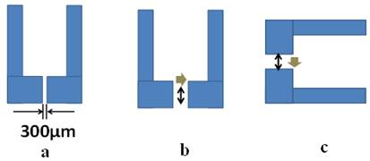
stray light. As the result of having tried various shape electrodes, only the
shape as shown in Figure 1a successfully aligned the non-spherical
nanoparticle. The direction of the stream to the polarization of incident beam
is changed by turning the electrode. We applied electric field of 2.4×10⁵
V/m between electrodes. The particles are expected to flow in the direction of
the gray arrow shown in Figs. 1b and c. In this experimental configuration, we
can observe the information about the length of particle along the polarization
direction of the incident beam. If the particles are aligned with the stream,
the excitation geometry of Figure 1b could obtain the information of the short
axis, while the information of the long axis can be obtained from the geometry
of Figure 1c.
was
defined as the angle between the propagation directions of the scattering light
and the incident beam. The scattering light was observed for the angular region
20°-60° for
present system. The optical cell had an anti-reflection coating for the
wavelength 532 nm. We observed the polarization direction of the scattering
light perpendicular to the polarization of the incident beam to eliminate any
stray light. As the result of having tried various shape electrodes, only the
shape as shown in Figure 1a successfully aligned the non-spherical
nanoparticle. The direction of the stream to the polarization of incident beam
is changed by turning the electrode. We applied electric field of 2.4×10⁵
V/m between electrodes. The particles are expected to flow in the direction of
the gray arrow shown in Figs. 1b and c. In this experimental configuration, we
can observe the information about the length of particle along the polarization
direction of the incident beam. If the particles are aligned with the stream,
the excitation geometry of Figure 1b could obtain the information of the short
axis, while the information of the long axis can be obtained from the geometry
of Figure 1c.
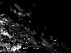
The sample used for experiment was TiO2 nanoparticle of needle-like shape. The SEM image of sample was shown in Figure 2. It was estimated that the length of long axis was around 400–500 nm, while the length of short axis was around 50 nm respectively.
3. Results and Discussion
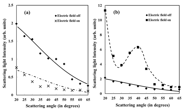
Experimental results for the electrode geometries in Figure 1b and c are shown in Figure 3(a) and (b) respectively. The signal intensities are normalized to the intensity of the signal without electric field when the scattering angle is 40°.
For the geometry in Figure 1b, the signal intensity monotonically decreases as increasing the scattering angle as shown in Figure 3(a). When the electric field is applied, the signal intensity becomes smaller over the scattering angle than those without electric field. Conversely, for the geometry of Figure 1c, the signal intensity increases by the applied electric field as shown in Figure 3(b). In addition, the local maximum appears at around 40°.
In order to analyze the experimental results, we used the theoretical calculation program, "Mie Plot", which gives the angular dependence of the scattering intensity due to a fine particle with spherical shape. This program has been developed based on the algorithms of Bohren and Huffman [3, 4, and 5]. The parameters needed in the calculation are the wavelength of excitation light, the refractive indexes of the material and the surrounded medium, and the particle diameter. As mentioned above, the scattering intensity depends on the particle diameter in the polarization direction of incident beam for Rayleigh-Mie scattering. The non-spherical nanoparticle such as needle-like particle has long and short axes. Thus in present study, we assume that the light scattering when the polarization direction is fix to the direction of long (short) axis of a non-spherical particle corresponds to that from a spherical particle which has the diameter equal to the length of long (short) axis. The theoretical calculation using Mie Plot was performed by changing the diameter. The values of parameters for calculation except for diameter are as follows.
Refractive index of TiO2: 2.6
Refractive index of water: 1.33
Wavelength of excitation light: 532 nm
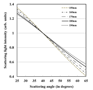
First, the experimental result shown in Figure 3(a) is analyzed. Without application of the electric field, the nanoparticles move freely in solution. Thus, the effective length of free rotational non-spherical particle is needed in order to evaluate the results of the light scattering measurement. From SEM image shown in Figure 2, roughly estimated effective length is around 180 nm. (The detailed of the estimation is mentioned later.) Thus the angular dependence of the scattering intensity for the diameter from 150 nm to 190 nm was calculated as shown in Figure 4. Since the result at 20° may be contaminated by excitation light, the calculation is performed between from 25° to 65°. It is noticed that the slope of each line changes as changing the diameter. One can find that the slope of experimental data is in good agreement with theoretical calculation when the diameter of nanoparticle is 160 nm.
When the electric field is applied, it is expected that the length of short axis can be measured from light scattering. Since the length of short axis is also roughly estimated to 50 nm from the SEM image, the angular dependence of the scattering intensity for the diameter from 30 nm to 70 nm is calculated. Because of Rayleigh scattering region, the change of the slope is too small to compare the results of experimental data and theoretical calculation in the present experimental system. Therefore, we use 50 nm as the length of short axis from the SEM image.
The results of calculations, where that the diameters are set to 160 nm (electric field off) and 50 nm (electric field on) are shown in Figure 5(a). Assuming that the distribution of the diameter of nanoparticles used in the experiments, the calculation denoted as 160 nm is an average of scattering intensities for the diameter ranging 155–165 nm. Similarly, for the calculation as 50 nm is an average of the signal range 45–55 nm. The behavior of the angular dependence of the scattering intensity obtained in the experiment shows qualitatively agree with that of theoretical calculation for the case of 160nm. However, it is noticed that the relative intensity of each signal was different when compared with the results of Figure 3(a) and Figure 5(a). This difference could be caused by the partial alignment of nanoparticles in solution. Some of the nanoparticles are aligned by the application of electric field, while some others are not. Since both, the aligned particles and the non-aligned particles, contribute to the signal, we introduce the factor of alignment ratio h for the improvement of the theoretical calculation. Considering the ratio h of alignment, the effective signal intensity IELS of each scattering angle can be written as
|
|
(1) |

Here I LS is the signal intensity calculated for the diameter which corresponds to the length of the short axis. INE is the signal intensity calculated for the diameter which corresponds to the diameter of free rotational particle. The effective length of free rotational particle is discussed later.
In order to determine the
suitable value of  ,
Eq. (1) was fitted to the experimental data with the least-square method. The
suitable values are
,
Eq. (1) was fitted to the experimental data with the least-square method. The
suitable values are![]() and
and
![]() for
the case of Figure 3(a) and Figure 3(b), respectively. Since the measurement of
the scattering intensity were performed using the same electrodes, the value of
for
the case of Figure 3(a) and Figure 3(b), respectively. Since the measurement of
the scattering intensity were performed using the same electrodes, the value of
![]() should
be used for analyzing the experimental data.
should
be used for analyzing the experimental data.
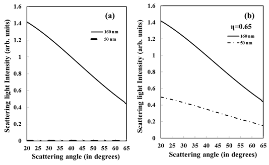
The calculation result for η=0.65 is shown in Figure 5 (b). The dashed line of Figure 5 (b) is modified values of calculation results of 50 nm. As a result, the relative signal intensity is similar to that of experimental result.
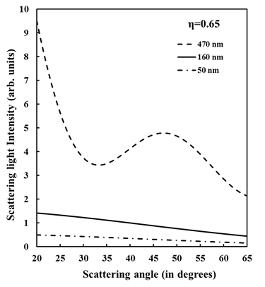
Next, the experimental result of electrode geometry of Figure 1c is analyzed by the same way. The length of the long axis is estimated to 400 nm ~ 500 nm from SEM image. As the results of theoretical calculations for the diameter from 400 nm to 500 nm, the signal profile was considerably similar to that of experimental result of Figure 3(b) in the case of application of the electric field when the diameters were set to 470 nm. The same value of alignment ratio (η=0.65) is also used for calculation. In the case of no electric field, the same value as Figure 3 (a) case (160 nm) is used. Again, the results for diameters of 470 nm and 160 nm are an average of the result for 450–490 nm and 155–165 nm, respectively.
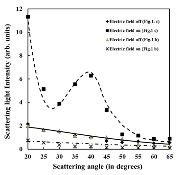
All experimental results under four different conditions are shown together in Figure 6. The results of theoretical calculation for three parameters are shown in Figure 7. When we use alignment ratio η=0.65, theoretical calculation results of both short and long axes behave in nearly the same way to the experimental results.
The reason why the observed length of the free rotation particle is 160 nm can be considered as follows. The direction of polarization of the incident beam is fixed. As the scattering light intensity depends on the projective component with respect to the direction of polarization of the incident beam, the projective component is determined by the average of the sine component of the length of the long axis. The average of sine component can be written as
|
|
(2) |
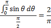
We have to consider rotation in the perpendicular plane and
the parallel plane against the propagation direction of the incident beam
because of 3-dimensional rotation. In considering the projection to both
planes, the effective length of the rotating particle is considered to be ![]() times the length of the long axis. Because the length of the long axis is 470
nm, the free rotation length should be 470 nm × 0.405 ~190 nm. The experimental
value of 160 nm is nearly the same as calculation value.
times the length of the long axis. Because the length of the long axis is 470
nm, the free rotation length should be 470 nm × 0.405 ~190 nm. The experimental
value of 160 nm is nearly the same as calculation value.
The experimental result and theoretical calculation show qualitatively same behavior. It can be said that the needle-like TiO2 nanoparticles are aligned because of rotation and migration due to the electric field.
The mechanism of alignment is not yet clear. The electrophoresis and dielectrophoresis are considered as the cause of migration of nanoparticles.
The electrophoresis is caused by the Zeta potential of nanoparticle. It is reported that the Zeta potential of the TiO2 particle is small in neutral solutions [6]. Water is used as the solution in this experiment. Therefore, it is hard to consider that the electrophoresis due to Zeta potential of TiO2 is caused in pure water.
Dielectrophoresis is produced by the difference of permittivity between the particle and the ambient medium and by the gradient of the electric field [7]. Since, there is no gradient of the electric field because of the shape of the electrode in this experiment, it is considered that the dielectrophoretic force must be small.
Most probable explanations of alignment may be considered as follows. The dielectric polarization is induced in the particle by the electric field. The non-spherical nanoparticle rotates by the torque due to electric field at the position of center between electrodes. At the position of slightly stir from the center, nanoparticle is rotated and pulled by the Coulomb force from the electrode.
4. Conclusion
Comparing the experimental data and the theoretical calculations, we conclude that the TiO2 needle-like nanoparticles are aligned because of the rotation and the migration in solution under the electric field. The behavior of the light scattering signal shows the alignment of the needle-like nanoparticles. However, the signal intensity is slightly different from the theoretical calculation. Therefore, we have to increase the precision of the measurement for the accurate estimation of the size of non-spherical nanoparticles by improving the measurement system.
Acknowledgements
T. Nakano is supported by Nippon Sheet Glass Foundation for Materials Science and Engineering.
References
[1] G. Mie "Beiträge zur Optik trüber Medien, speziell kolloidaler Metallösungen", Annals of Physics, 25, 1908, 377–445 [in German]. View Book
[2] T.B. Jones "Electromechanics of Particles" Cambridge University Press, 1995. View Book
[3] P. Laven "MiePlot A computer program for scattering of light from a sphere using Mie theory & the Debye series" 2012, [Online]. View Book
[4] P. Laven "Simulation of rainbows, coronas, and glories by use of Mie theory" Applied Optics, 42, 2003, 436-444. View Book
[5] C.F. Bohren and D.R. Huffman, "Absorption and Scattering of Light by Small particles" Wiley, New York, 1983. View Book
[6] W. Janusz, A. Sworska and J. Szczypa "The structure of the electrical double layer at the titanium dioxide/ethanol solution interface" Colloids and Surfaces A: Physicochemical and Engineering Aspects, 152, 1999, 223–233. View Book
[7] H.A. Pohl "The Motion and Precipitation of Suspensoids in Divergent Electric Fields" Journal of Applied Physics, 22, 1951, 869–871. View Book