International Journal of Theoretical and Applied Nanotechnology (IJTAN)
ISSN: 1929-1248

Volume 1, Issue 1, Year 2012 - Pages 86-89
DOI: 10.11159/ijtan.2012.013
Optical and Electrochemical Characteristics of Nanostructural TiO2/Ti/Glass Electrode
Byung-Ho Moon, Dong-Joo Kwak, Youl-Moon Sung
Electrical Engineering, Kyungsung University
Busan 608-736, Korea
ymsung@ks.ac.kr
Abstract - In this work, a design of transparent conductive oxide less electrochemical luminescence (TCO-less ECL) cell has been proposed using a TiO2/Ti electrode. Ti films (~500 nm in thickness) are deposited on a glass substrate without Fluorine-doped SnO2 (FTO) by RF magnetron sputtering. The as-prepared films were characterized by XRD, FE-SEM, XPS, and BET analyses. The as-fabricated ECL cell is composed of a FTO glass/Ru(II) complex/nanoporous TiO2/Ti/glass. The ECL efficiency of the TiO2/Ti-basd cell was ~265 cd/m2, much higher than the efficiency (135 cd/m2) of FTO-based cell. From the result, it can be found that the use of TiO2/Ti electrode significantly improves the ECL efficiency.
Keywords: Ti film, Nanoporous TiO2, TCO-less ECL, rf Magnetron Sputtering, Sol-Gel
© Copyright 2012 Authors - This is an Open Access article published under the Creative Commons Attribution License terms. Unrestricted use, distribution, and reproduction in any medium are permitted, provided the original work is properly cited.
1. Introduction
The electrochemical luminescence (ECL) cell is often fabricated with the transparent conductive oxide (TCO) glass and Ru(II) complex (Ru(bpy)32+) (Richter, 2004). The application of a porous TiO2 layer is reported to improve the luminescence efficiency (Kenichi et al., 2008, Kwon et al., 2010). The charge accumulation layer of ECL cell consisted of 15~20 nm-sized porous TiO2 layer attached with large number of Ru (II) complex molecules, enabling efficient light emitting. TCO layer is an important part in the construction of ECL cell. Indium-tin-oxide (ITO) and fluorine-doped tin-oxide (FTO) are most commonly used for ECL cell. Both TCO materials can be fabricated by plasma-aided process technologies such as, sputtering, ion plating or chemical vapour depositions (Heo et al., 2009, Han et al., 2009). However, these TCO glasses are expensive and the use of two TCO glasses for ECL cell is not suitable in the viewpoints of not only transparency but also cost-effectiveness (Kroon et al., 2007, Kwon et al., 2010). Further studies are required in terms of efficiency and cost-effectiveness. In this work, as an effort to replace TCO, the Ti metal films were deposited on the secondary glass substrate without TCO by radio-frequency (RF) magnetron sputtering, which was followed by coating of nanoporous TiO2 layer. Processing and electrical characterization of the ECL cell using this TiO2/Ti photoanode structure are investigated.
2. ECL Concept and Structure
The concept on general ECL involved electron transfer reactions between an oxidized Ru(bpy)33+ and a reduced Ru(bpy)3+, both of which were generated at an electrode by alternate pulsing of the electrode potential. The mechanism is outlined below (Richter, 2004):
|
Ru(bpy)32+ - e- → Ru(bpy)33+ E°Ru2+/3+ = +1.2V vs SCE. |
(1) |
|
Ru(bpy)32+ - e- → Ru(bpy)3 E°Ru2+/1+ = -1.4V vs SCE. |
(2) |
|
Ru(bpy)33+ + Ru(bpy)3+ → Ru(bpy)3*2+ +Ru(bpy)32+ |
(3) |
|
Ru(bpy)3*2+ → Ru(bpy)32+ + h (~2.1eV, 620nm). |
(4) |
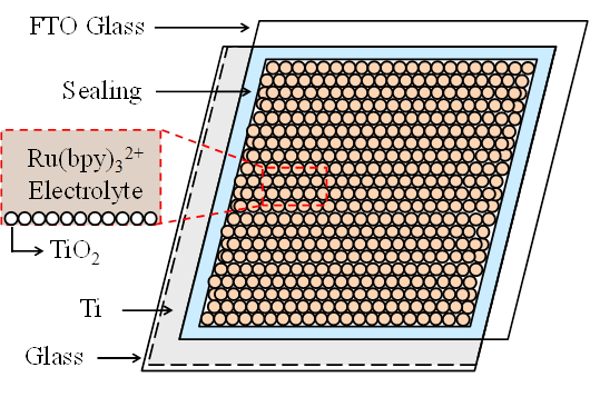
Here, Ru(bpy)3*2+ represents the excited molecule that emits light, and h is a photon of light. The excited state formed in this ECL reaction is similar to that formed during photoexcitation (i.e., photoluminescence or PL). Recent ECL cell uses a layer of porous TiO2 deposited on a TCO glass as a charge accumulating layer. This porous TiO2 layer with 15~20 nm-thickness is interconnected in three dimensions with Ru(bpy)32+ molecules. The large number of Ru(bpy)32+ molecules injected into the porous TiO2 layer becomes attached to the large surface area of porous structure, which enables efficient light emitting. Figure 1 shows an ECL cell using the layers of Ti metal and porous TiO2 with Ru(bpy)32+. In order to enhance the ECL efficiency, a layer of porous TiO2 is coated on Ti metal film to increase the interfacial area with the Ru(bpy)32+ and conductivity of electrode. The electrode with Ti metal and n-type semiconductor TiO2 can inject high density of electrons to Ru(bpy)3(PF6)2 electrolyte through the large surface of porous TiO2. The fabricated ECL cell in this report is thus composed of glass/ Ti-metal/ porous TiO2/ Ru(bpy)3(PF6)2/ FTO electrode.
3. Experimental
Figure 2 shows a schematic diagram of fabrication procedures of the ECL cell using TiO2/Ti electrode. The electrode of cell is prepared in the following processes. A Ti metal film with a thickness of 500 nm was deposited on the glass substrate by RF magnetron sputtering at a substrate temperature of 300°C. A layer of TiO2 pastes with a thickness of ~15 µm (Solaronix D-paste) was then coated on to the as-coated layer of Ti/glass substrate by Dr. Blade method, followed by a heat treatment at 450°C for 30 min. The sol-gel combustion method was used to produce the porous TiO2. The TiO2 gel was sintered at 450 °C for 150 min. resulted in the uniform spherical morphology of the nanoparticles, as well as the uniform distribution with ~15 nm in diameter.
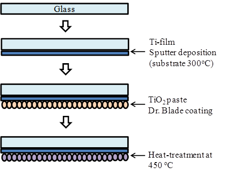
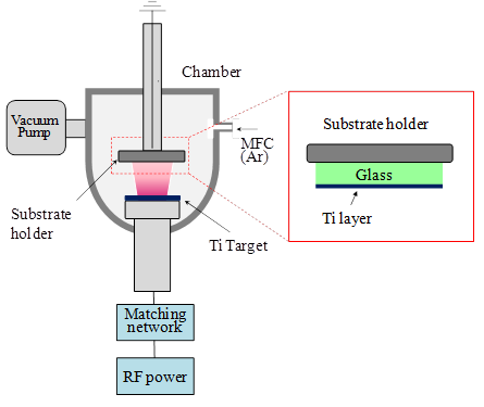
Figure 3 shows a schematic illustration of RF magnetron sputter system. The film deposition using RF magnetron sputter system has been described in detail elsewhere (Heo et al., 2009), and can be briefly described as follows. Firstly, pre-sputtering was done for 10 min with a shutter covering the substrate in order to remove surface contaminants of the target. The Ti film was deposited in Ar gas pressure of 5 mTorr for 30 min at the substrate temperature of 300°C. RF power between the target and substrate was maintained at 300 W. The distance between substrate and target surface was 10cm. The deposition condition of Ti metal films by RF magnetron sputtering is summarized in Table. 1. The microstructures of Ti film prepared by RF magnetron sputtering were characterized by field emission scanning electron microscope (FE-SEM). X-ray diffraction (XRD) and X-ray photoelectron spectroscope (XPS) were used to investigate the crystallographic structure and components of the films. The resistivity of Ti film was measured using four point probe. Impedance of the each layer of the ECL cell was analyzed by electrochemical impedance analyzer (EIA; IM6, ZAHNER). Light emission of the ECL cell was observed by spectral brightness analyzer (Konica Minolta, CS-2000A).
4. Results and Discussion
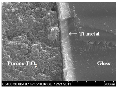
Figure 4 is a SEM micrograph showing the cross-section of the as-deposited porous TiO2/Ti/glass electrode. The thickness of the Ti metal layer was 500 nm, and the deposition rate of Ti film was 16.7 nm/min. The Ti film conductivity was measured using four point probe method. The sheet resistance decreases as the film thickness increases. The sheet resistance (1.2 Ω/Sq.) was obtained from the Ti layer in 500 nm thickness. The sheet resistance of FTO layer generally used for ECL cell fabrication was measured in the range of 10-30 Ω/Sq. In addition, based on XRD observation (not shown), it was found that the (010), (002) and (011) orientation of the titanium increased with the increase in substrate temperature up to 300°C. On the other hand, the (010) and (002) orientations increased while the (011) orientation decreased at a higher temperature range (>300°C). It is assumed that the columnar growth of the film yields the (010) and (002) peaks, while the surface adatom mobility of the film by substrate temperature yields the (011) peak.
An FE-SEM image of the TiO2 layer is displayed in Fig. 5. TiO2 paste prepared by sol-gel combustion method was coated with a thickness of 10 μm on a glass by Dr. Blade method, followed by a heat treatment at 450°C for 30 min. The sample has a sponge-like texture with numerous small pores. As shown in Fig. 5, the nanoporous TiO2 layer consists of uniform particles in the range of 30~50 nm size. Average particles size and BET analysis results are summarized in Table 2. The pore diameter was controlled by annealing temperature. After annealing treatment, the mean particle diameter increases from 50nm for 550°C to 150°C for 700°C, a significant change occurring between 550 and 700°C. Mean pore size is found to be 30~35 nm for 550°C. The FE-SEM photograph of the porous TiO2 films exhibited a fractured appearance as shown in Fig. 5. The fracturing of the TiO2 surface is often caused by contraction and stress under drying (Byrne et al, 1998). It thus seems that the fracturing occurred during the annealing process due to the different thermal coefficients of expansion of the TiO2 and Ti layers.
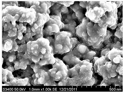
Table. 1. BET surface area, pore volume, pore size and particle diameter of the nanoporous TiO2 sample.
|
BET (m2/g ) |
Total pore volume (cm3/g) |
Mean pore diameter (nm) |
Mean particles diameter (nm) |
|
200~250 |
0.25~0.35 |
20~30 |
50~80 |
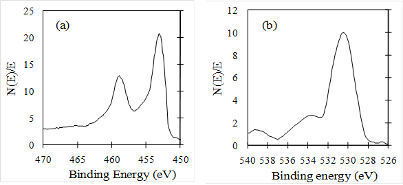
Figure 6(a) and 6(b) show the XPS of Ti2p and O1s on the surface of TiO2/Ti film, respectively. Ti2p peak at the binding energy of 457 eV is sharp and strong, indicating that the Ti element mainly existed as the chemical state of Ti+ (Rahman et al, 1999). The O1s peak at the binding energy of 530 eV is somewhat asymmetric, the left side was wider than the right as show Fig. 6(b), indicating that at least three kinds of oxygen peaks correspond to 530, 532 and 533 eV, respectively were exist in the near surface region by resolving XPS curve. The peak at 530 eV was due to oxygen in the TiO2 crystal lattice, the second peak at 532 eV was due to surface hydroxyl, and the other peak at 533 eV was due to physically adsorbed oxygen (Zili et al, 1999). The atom ratio of Ti to crystal lattice oxygen was about 1:1.8, which was caused by some oxygen deficiencies in the surface region.
The measured electrochemical impedances of as-fabricated ECL cell using nanoporous TiO2/Ti electrode are summarized in Table 3. The three semicircular shapes assigned to impedance related to charge transport at the counter electrode (R1), at the TiO2/ Ru(II)/ electrolyte interface (R2) and the carrier transport by ions in the electrolyte (R3) could be obtained from the measured impedance curve. The Rh is assigned to resistance of Ti thin film and the contact resistance between the Ti thin film and TiO2. For case TiO2/Ti-based cell, the values of R1, R2, R3 and Rh were about 13.9, 17.1, 10.2 and 8.9 Ω. For case FTO-based cell, those of R1, R2, R3 and Rh were about 15.2, 16.8, 9.8 and 15.4 Ω as shown Table 3. The cell with TiO2/Ti electrode had low impedance due to the high conductivity of the dense Ti layer compared with FTO-based cell. It can be seen that the TiO2/Ti electrode with high porosity and conductivity shows the good impedance characteristics in this experiment.
Table 2. Impedances of TiO2/Ti-based cell and FTO-based cell.
|
Sample |
Rh (Ω) |
R1 (Ω) |
R2 (Ω) |
R3 (Ω) |
|
TiO2/Ti |
8.9 |
13.9 |
17.1 |
10.2 |
|
FTO |
15.4 |
15.2 |
16.8 |
9.8 |
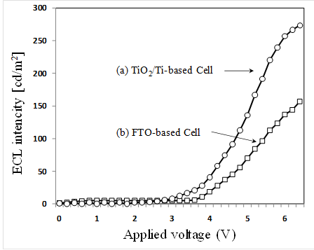
The ECL intensity variations of two different types are shown in Fig. 7 as a function applied voltages. Figure 7(a) and 7(b) are the intensity variations of the cells using the porous TiO2/Ti for the cathode electrode and using only FTO glass for both electrodes, respectively. The ECL intensities can be observed as follows. ECL intensities of 265 cd/m2 obtained for the porous TiO2/Ti-based cell is larger by about 2 times than the FTO-based cell (135 cd/m2) at 6V bias. In addition, the 2.3 threshold voltage measured for the TiO2/Ti-based cell is lower than that of FTO based cell (2.7V). It can be seen that the use of TiO2/Ti electrode considerably improves the ECL efficiency. On the other hand, it is not sufficient to obtain more quantitative index for the optimization of the TCO-less ECL cell, although the above-described experimental result is useful to discuss about the effectiveness of TCO-less structure for efficient ECL. It is necessary to do more research on the ECL behaviour and control based on more detailed experimental data. This will be checked experimentally at various ECL structures and operating condition in further research.
5. Conclusion
The electrochemical cell using the electrode of Ti metal, porous TiO2 and Ru (II) complex (Ru(bpy)32+) was fabricated for the high efficient ECL. Ti metal films (500 nm in thickness) are deposited on a glass substrate without FTO by RF magnetron sputtering. The fabricated ECL cell is composed of a FTO glass/ Ru (II) complex/ porous TiO2/ Ti/ glass. The ECL intensities of 265 cd/m2 obtained for TiO2/Ti-based cell is larger by about 2 times than FTO-based cell. It can be found that the use of TiO2/Ti electrode significantly improves the ECL efficiency.
Acknowledgements
This research was supported by Basic Science Research Program through the National Research Foundation of Korea (NRF) funded by the Ministry of Education, Science and Technology (2010-0012200).
References
Byrne, J. A., Eggins, B. R., Brown, N. M. D., Faure, L., Kazovan, H., (1998). Immobilisation of TiO2 powder for the treatment of polluted water, Applied Catalysis: B Environmental, 17, 25-36. View Article
Han, D. W., Heo, J. H., Kwak, D. J., Han, C. H., Sung, Y. M., (2009). Texture, Morphology and Photovoltaic Characteristics of Nanoporous F:SnO2 Films, Journal of Electrical Engineering & Technology, 4, 93-97. View Article
Heo, J. H., Jung, K. Y., Kwak, D. J., Lee, D. K., Sung, Y. M., (2009). Fabrication of Titanium-Doped Indium Oxide Films for Dye-Sensitized Solar Cell Application Using Reactive RF Magnetron Sputter Method, IEEE Transactions on Plasma Science, 37, 1586-1592. View Article
Ide, K., Fujimoto, M., Kado, T., Hayase, S. (2008). Increase in Intensity of Electrochemi-luminescence from Cell Consisting of TiO2 Nanohole Array Film, Journal of the Electrochemical Society, 155, 645-649. View Article
Kroon, J. M. et al., (2007) Nanocrystalline Dye-sensitized Solar Cells Having Maximum Performance, Progess in Photovoltaic: Research and Applications, January, 15, 1-91. View Article
Kwon, H. M., Han, D. W., Kwak, D. J., Sung, Y. M., (2010). Preparation of Nanoporous F-doped Tin Dioxide Films for TCO-less Dye-sensitized Solar Cells Application, Current Applied Physics, 10, 172-175. View Article
Kwon, H. M., Han, C. H., Sung, Y. M. (2010). Fabrication of High Efficiency Electrochemi-luminescence Cell with Nanocrystalline TiO2 Electrode, KIEE International Transactions., 59, 363-368. View Article
Rahman, N. M., Krishna, K. M., Soga, T., Jimbo, T., Umeno, M., (1999). Optical properties and X-ray photoelectron spectroscopic study of Pb-doped TiO2 thin films, Journal of Physics and Chemistry of Solids, 60, 201-210. View Article
Richter, M. (2004). Electrochemiluminescence (ECL), Chemical Reviews, 104, 3003–3036. View Article